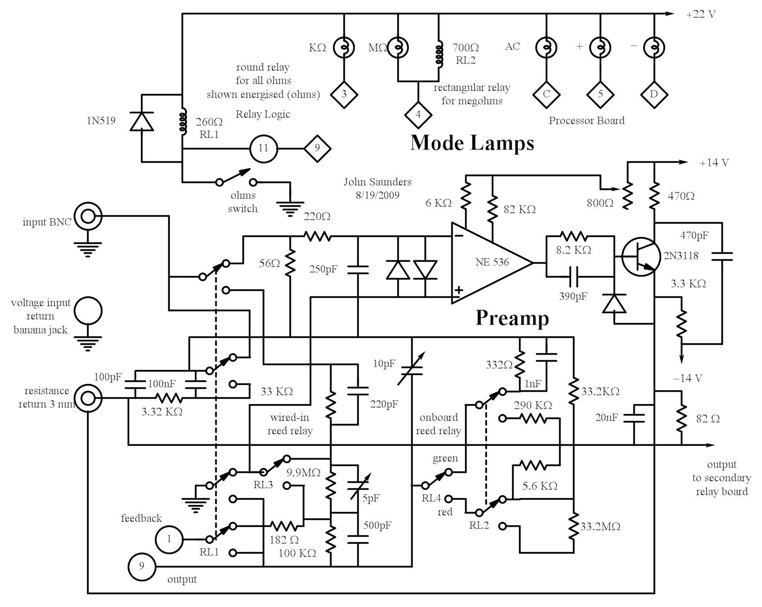
A description of the preamp is given in the sytem explanation.
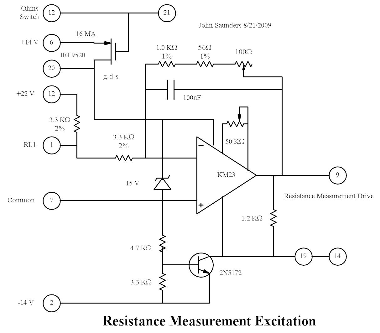
A description of the resistance excitation circuit is given in the sytem explanation.
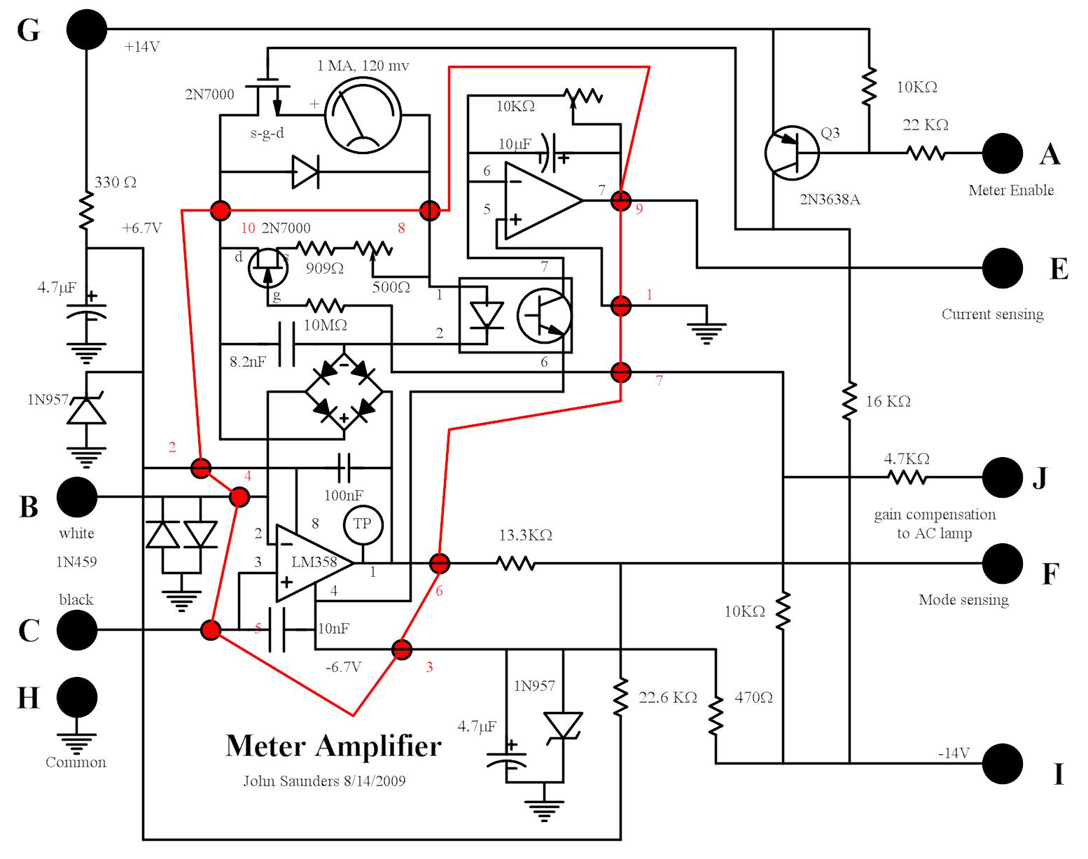
A description of the meter amplifier is given in the photos explanation.
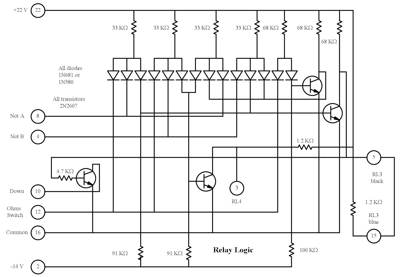
This is on the same board as the ohms excitation circuit, and is not changed. It uses DTL discrete logic to control the two preamp range relays, which do not operate in binary sequence.
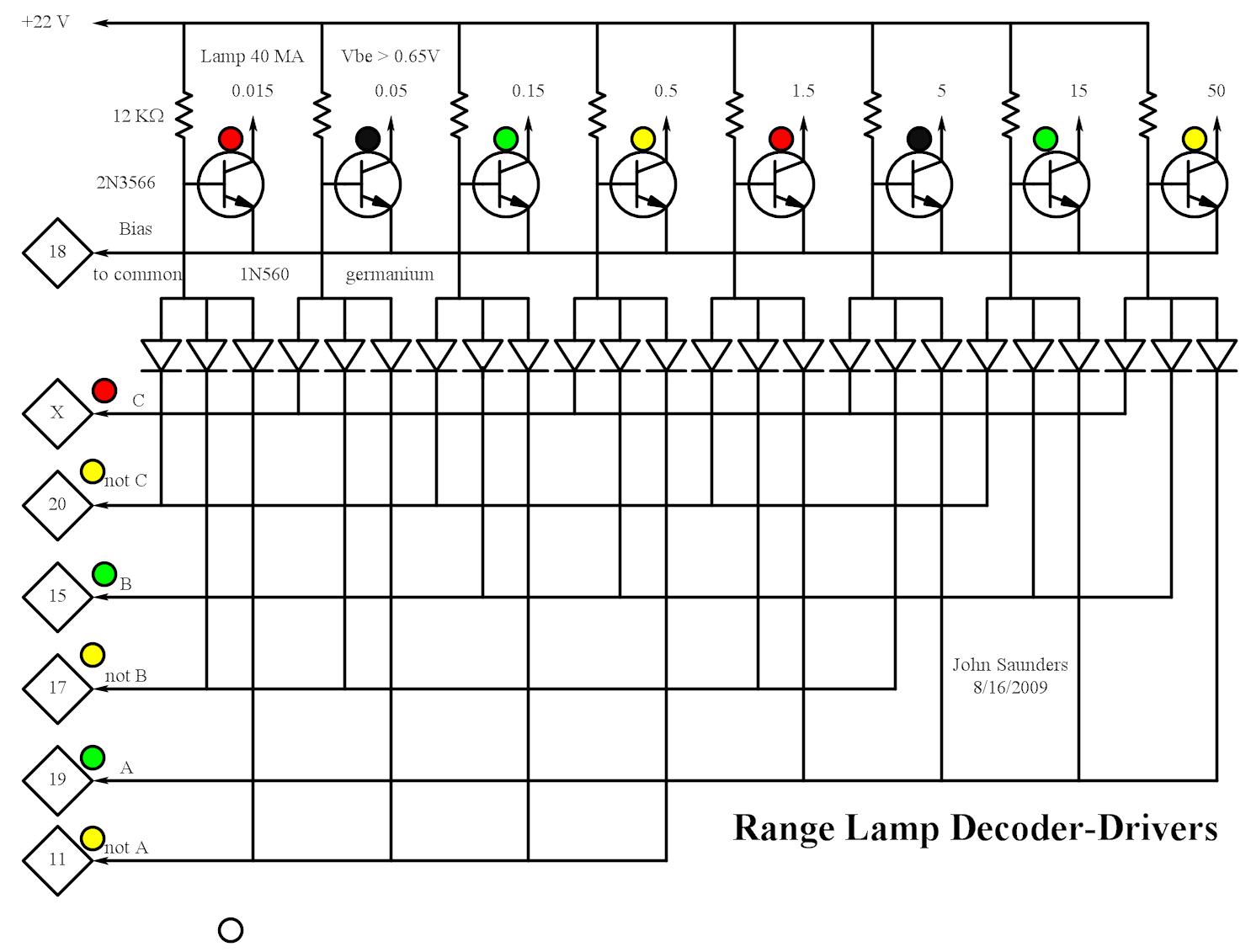
A description of the range decoder is given in the photos explanation.
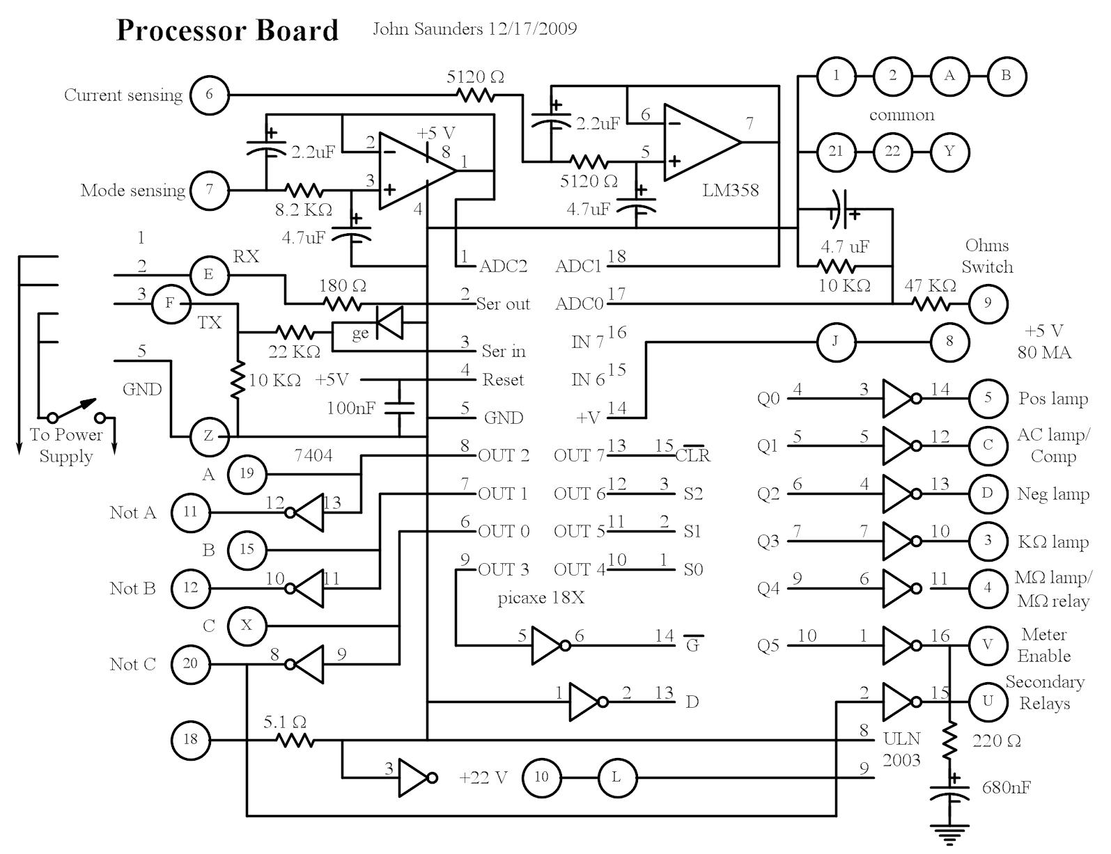
There are three inputs to the PICAXE:
Pin 0 is high in voltage mode, connected to the ohms relay coil.
Pin 1 is analog meter current from an opto-isolator and is low-pass filtered.
Pin 2 is the low-pass filtered output of the meter amplifier.
Due to the bridge rectifier and the opto-isolator diode there is
at least a 2.5 volt drop in the feedback path when in range.
On AC the mode voltage averages out to zero.
A bias results in a 0.5 to 4V span, neg high as the amplifier inverts.
There are 8 outputs.
Pins 0-2 are the range. They go to ancient diode NAND decoders to illuminate
a single range lamp and the coils of three reed relays which control the dividers.
Pin 3 is the gate of a 74259. This chip has a demux and 8 D registers, which can be
individually set. In this circuit, they can only be all cleared at once.
Pins 4-6 select the 74259 register to set. 0-4 are the mode lamps, 4 is the megohm
lamp and also the megohm relay. Output 6 is the meter enable. 5 & 7 not used
Pin 7 is the 74259 clear.
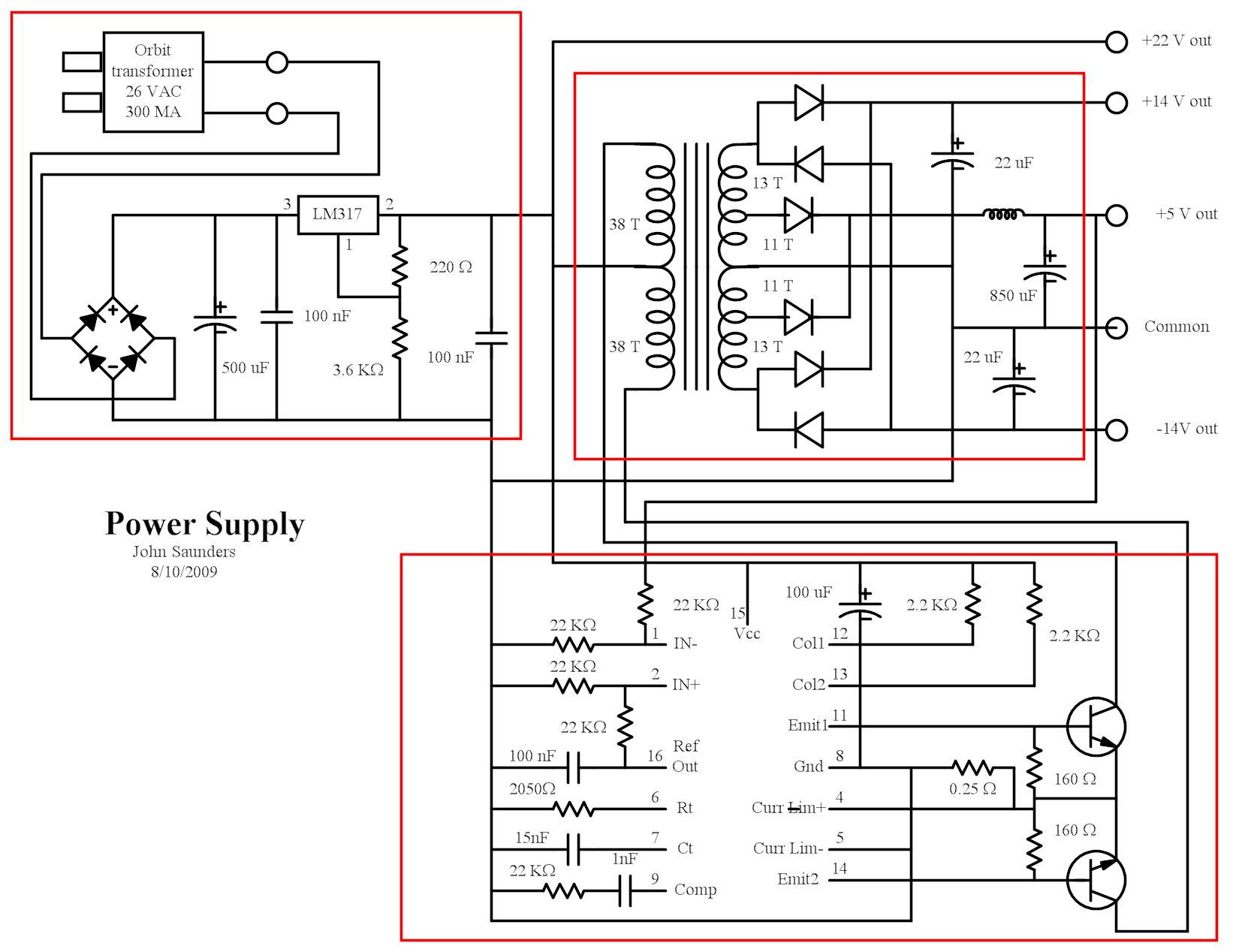
A description of the power board is given in the photos explanation.