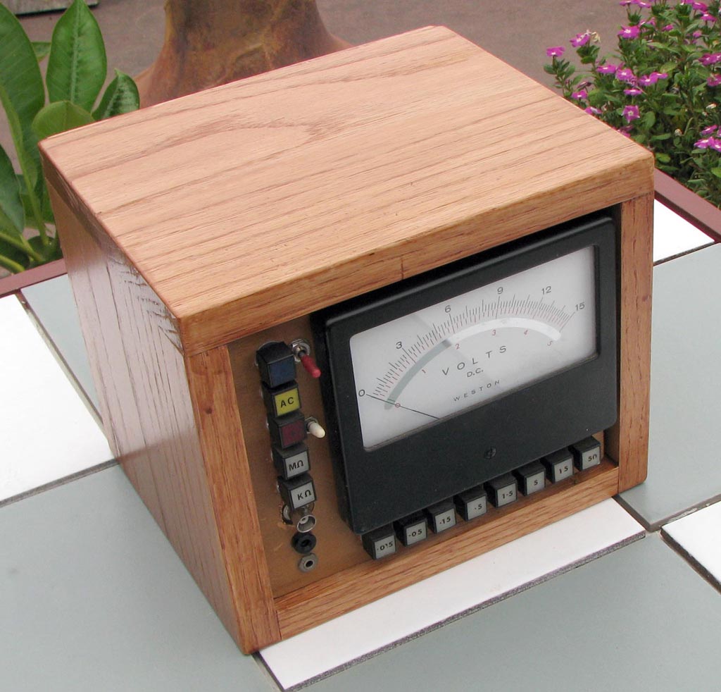
This shows the finished V-O-M. It was worth the effort in order to re-cycle the excellent meter and the military-quality indicators. The solid oak box is new, as the old one was much the worse for wear. Besides, the nice box adds a psychological justification for the effort.
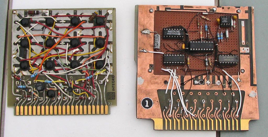
These are the original and PICAXE boards. The old one uses 12 RTL ICs to make a 3-bit up-down counter, not re-cycling. I had to butcher an old prototype board to use a modern proto-board because boards with .156“ edge connectors are long gone.
I originally thought that I could just replace this board, and the little meter with an opto-coupler, but, of course, there were complications .
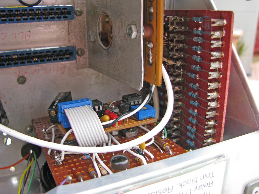
This shows some 60's era hardware which was kept. On the right is 8 3-input DTL NAND gates to decode the 3-bit range signal and drive the range indicators, which are 24 volt, 40 MA plug-in lamps. It is an actual piece of old hardware, Honeywell, I think.
At the top center is the 5 - 15 relay board which goes between the preamp and the meter amplifier. It was carved from an old piece of IMB equipment which had two reed relays on it.
At bottom center is the meter amplifier, bolted to the meter terminals. It uses an inverting amplifier with a bridge rectifier in the feedback loop.
I had intended to leave it as is, and just replace the small meter with an opto-isolator to detect the upper and lower limits. However, the original Burr-Brown modular op-amp was replaced in the 80's by a CA3010 integrated circuit, on the Vero stripboard underneath. It was a round package. Unfortunately, this chip had insufficient output to drive the opto-isolator, so I had to replace it with a LM358. Since this DIP chip did not fit the Veroboard spacing, it had to be put on a daughter board.
Also, the original design had discrete-component circuits to detect the mode: Negative, Positive, or AC. I decided to rip these components out and have the PICAXE do the detection.
In the end only the PNP transistor and one resistor remain from the original. In hindsight I should have started anew and used the two-op-amp ground-referenced rectifier circuit..
The original design had a transformer and rectifier with a single 30-volt output. 24 volts was required for the indicators and the two military-style relays for volts-ohm and kilohm-megohm switching. Plus and minus 15 volts was required for the original modular op-amps. Three discrete-component regulators provided these outputs. The RTL logic used 3.6 volts, provided by a dropping resistor. When the CA3010 was later added, it needed plus and minus 7 volts. Zener diodes were added for that.
Not surprisingly, this assembly ran so hot I resorted to parking a 115-volt fan behind the meter, so it had to go.
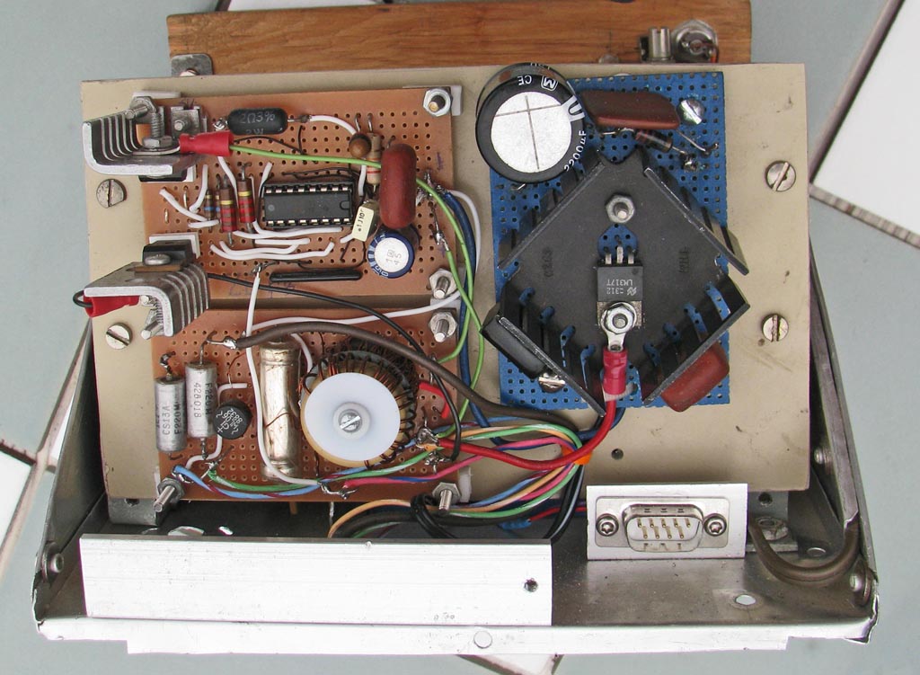
The replacement uses a plug-in 26 VAC transformer recycled from an irrigation controller my wife replaced because it was confusing. The blue board was recycled from my junk box. It provides 22 volts, the highest voltage which the transformer supports with enough regulator drop. It is enough for the lamps and relays.
The rest is an exercise in designing a switching regulator and winding its transformer and choke coil. It provides 5 volts for the PICAXE board regulated by the SG3424. The design is lifted from its spec-sheet, but the selection of the transformer and choke cores, and the number of turns was by trial and error. The efficiency is about 60% and the maximum output power far exceeds the 4-watt requirement.
Plus and minus 14 volts are provided by peak rectifiers driven by windings on the transformer. They are fairly well proportional to the regulated 22-volt supply. They are still needed by the legacy pre-amp and ohms excitation circuits, which are unchanged. It is on two boards only because the proto-boards come in that size.
The 26 VAC input uses pins 6-9 of the DA-9. It has to plug-in because the transformer won't go through a hole in the back of the cabinet. An adapter provides a programming socket. .