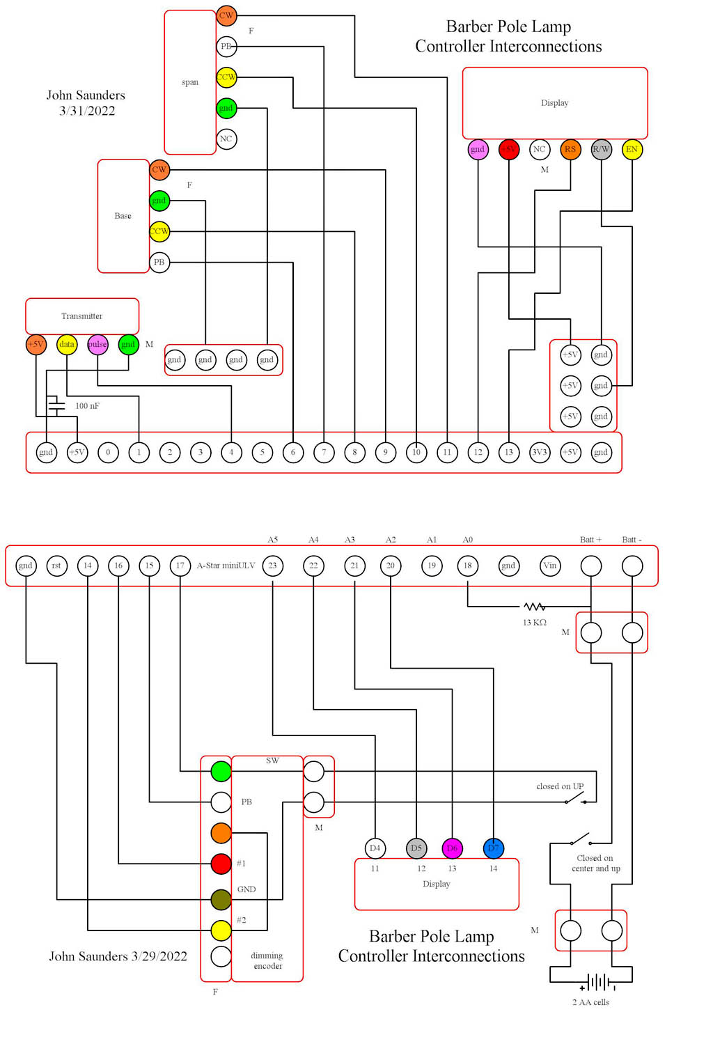
This splits the Pololu 32U4 A-Star mini ULV ports into two rows of connectors, which are female headers added to the sides of the chip, which is socketed.
There are some sockets on the left which are not directly connected to the chip.
These provide convenient power, and there are also additional power headers.
The switch is strange, since the center position has connections,
The port selection was dictated by needing interrupts for the 6 encoder pins.
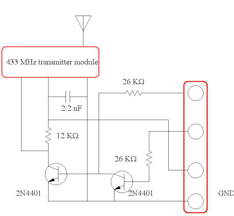
Due to the limitations of the Arduino UART, additional citcuitry is needed to generate the modulating signal.
The upper pin is the Tx data from pin 1 of the 32U4. Since it is the wrong polarity, it must be inverted.
After an Arduino pin is initialized for serial, it cannot be also used for digital write. The next pin is connected to pin 4 of the 32U4. Its purpose is to generate a prepulse which provides an interrupt to the receiver.
The transmitter and receiver modules are of a different brand from those in my other RF projects, and are inompatible.