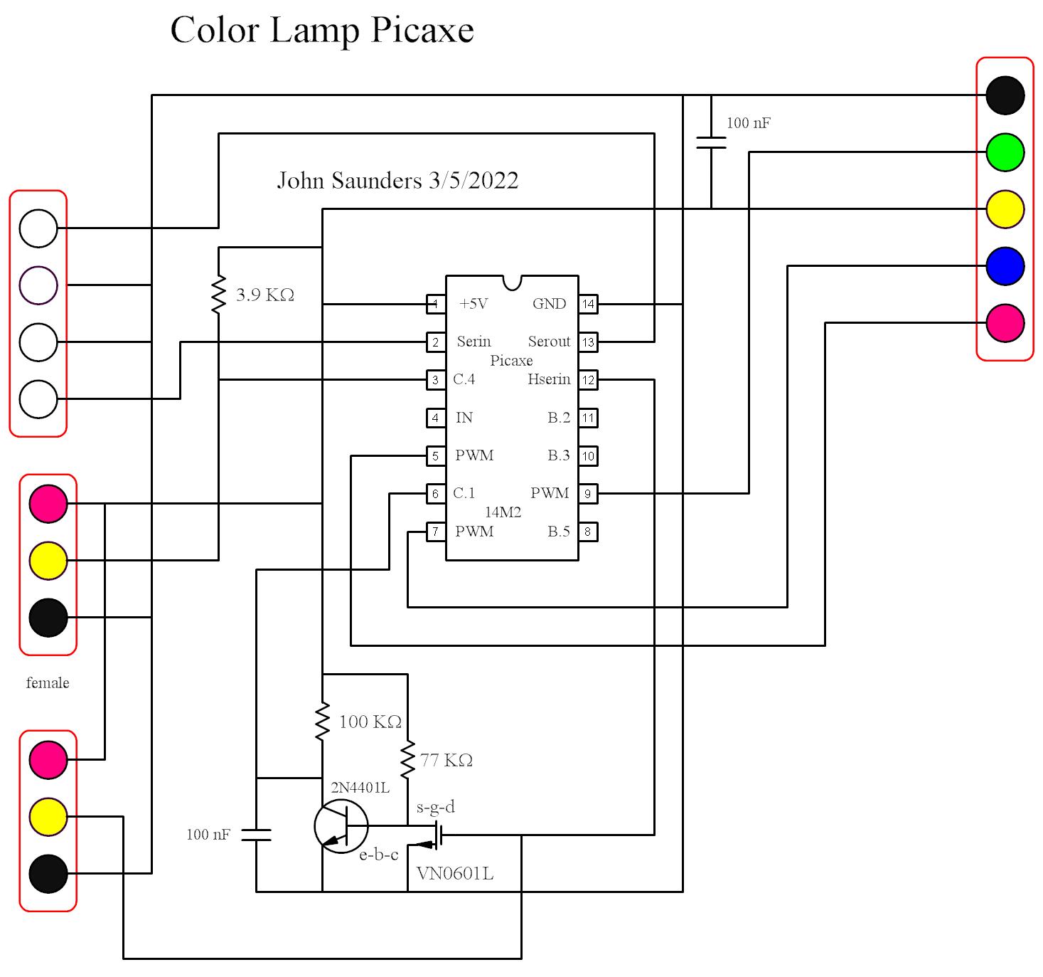
A Picaxe microcontroller was chosen for this because of the limitations of the Arduino UART.
The top left is a male header which is connected only for programming. It is connected to the computer via a home-made adapter which contains protection circuitry. Normally the two lower pins are jumpered together.
The top right is female header on the other end of a cable to the driver board.
On the middle left is a female connector for the pigtail terminating in a 18B20 temperature sensor.
The lower left male header is for the cable to receiver module in the striped pillbox. This is remoted for better reception
The circuit connected to the output of the receiver is an integrate-and-dump which provides an interrupt signal only for pulses greater than about 6ms. This eliminates most noise and interference from dominating the computer.
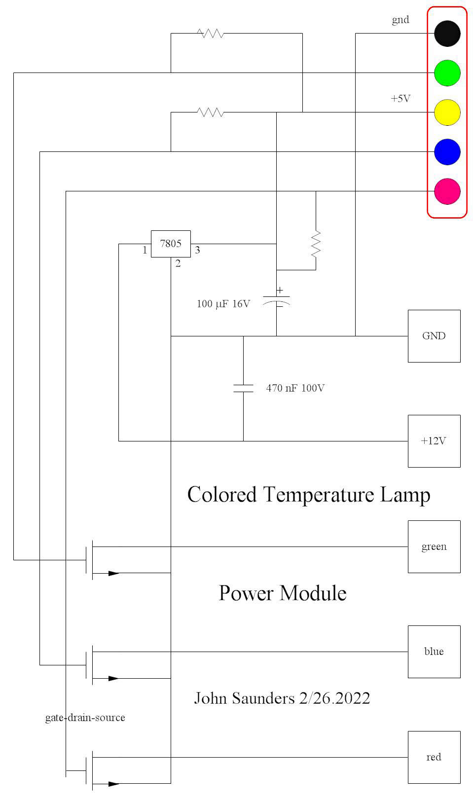
The three driver MOSFETS have turn-on voltages of about 2V, but have 4990 ohm pullup resistors anyway.
Their outputs go to a screw-terminal strip, which also connects to the external 12V 2.5A switching power supply via a 5.5 x 2.1 coax socket on the end of the box.
A 4-wire cable goes from this strip to the 6 LED strings, which have common anodes.