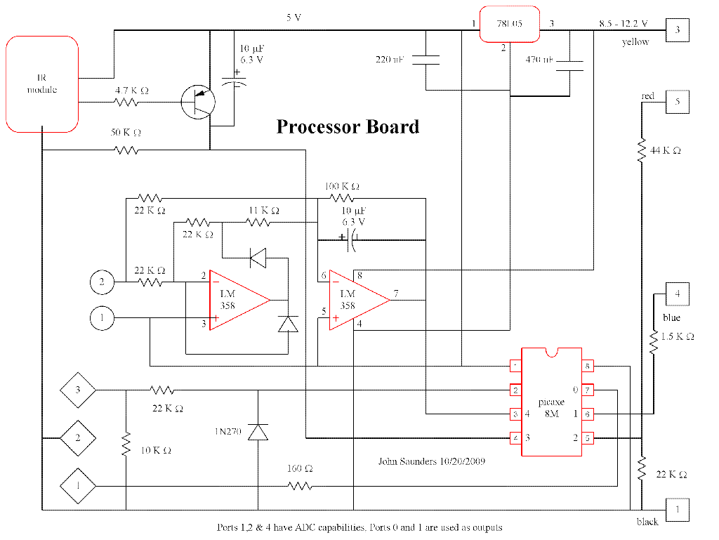
The IR sensor is of the type used in TVs, etc. Its output is a negative-going pulse train at 38 KHz . This is stretched so that the picaxe 08M can poll it at 100 ms intervals without missing it. The other input is a low-voltage AC from a tiny transformer. It is activly rectified by a two-op-amp circuit, and the resulting filtered DC voltage is measured with an ADC input. The 08M output drives the base of the relay-driver transistor in the coffee timer module.

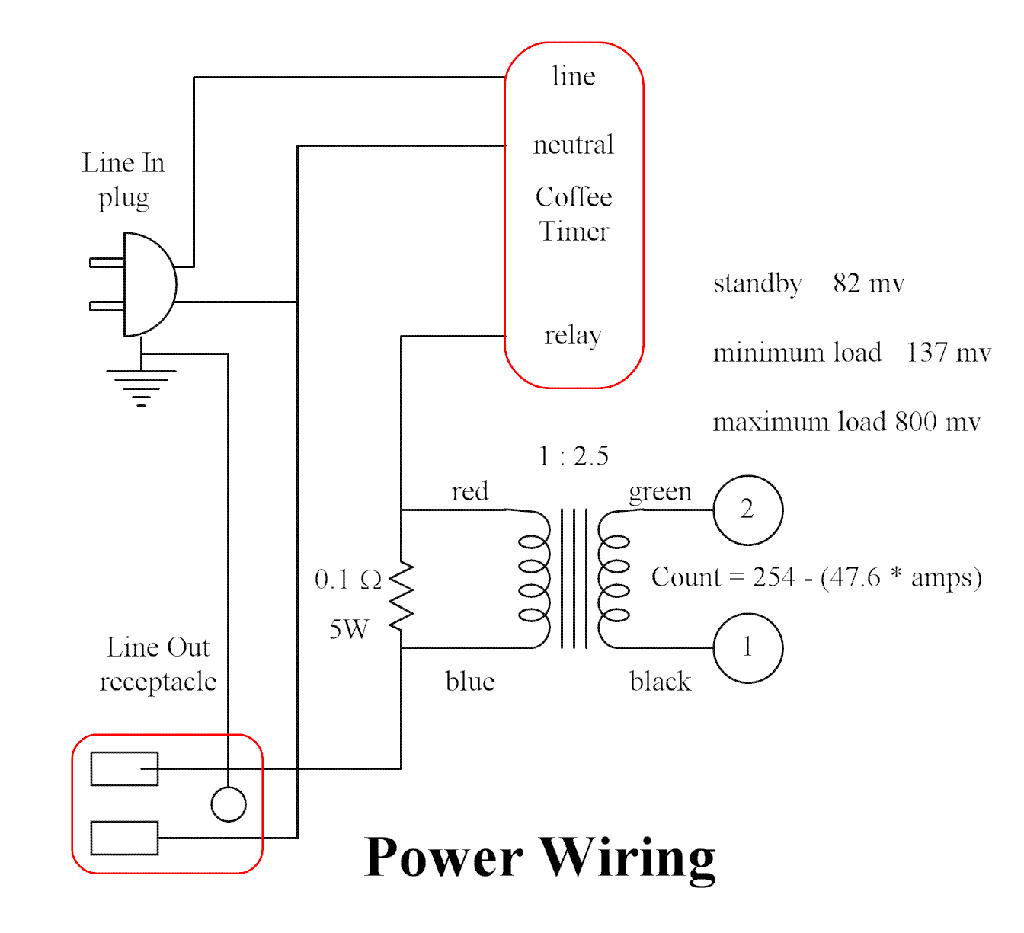
This shows the connections to the relay in the coffee timer and the current-measuring components..

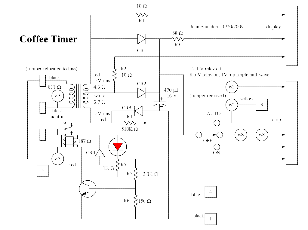
This is only the parts of this device that I traced and which are relevant to this use of it. The only changes are removing the wire from the internal timer to the relay driver transistor base, and re-routing the relay jumper to line instead of neutral.