These are the Gas Sensor circuit diagrams.
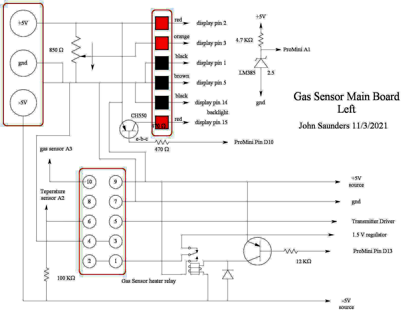
These circuits here are to the left (from the back) of the Main Board up to the Arduino. They comprise the power terminal block, the power distribution socket header and the 10-pin sensor header.
|
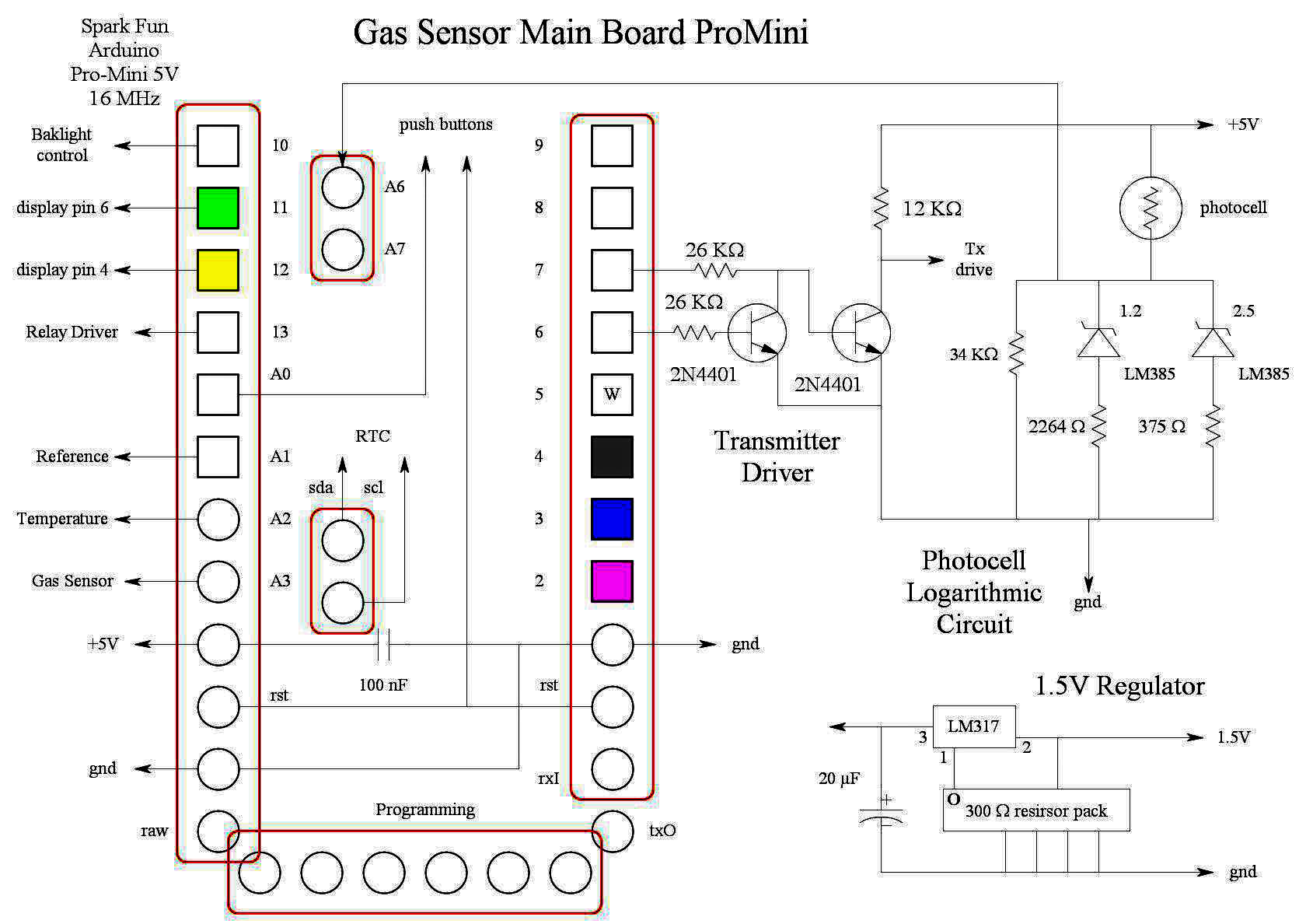
The Processor has 14 connections equipped with socket headers with long tails below which plug into sockets soldered in the Main Board. Six of these have jumper wires to the display.
|
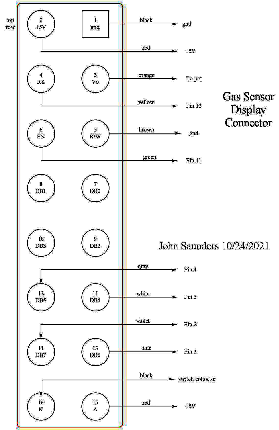
While most character LCD displays have 16 pins in a row, this one has a 16-pin header. The pin numbers for the signals are the same. I opted to use jumper wires which go directly to the processor or the power distribution socket header.
|
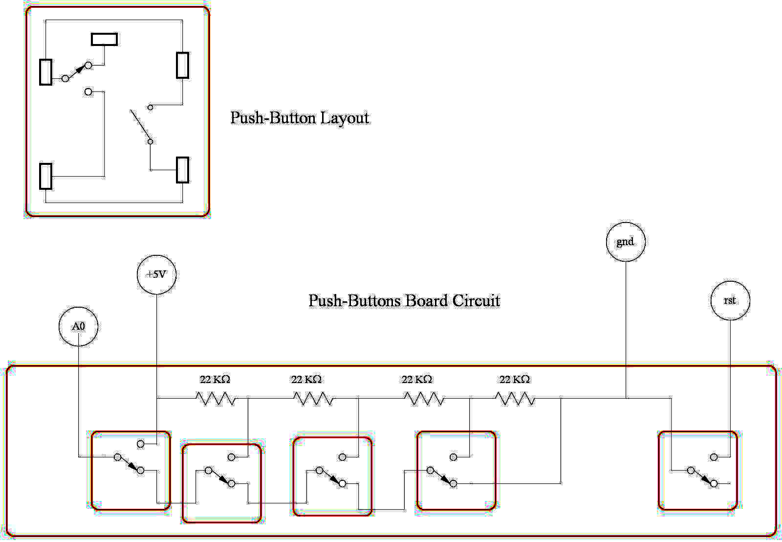
These push-buttons have a strange configuration, but have a light force, good tactile, and click. Being double-throw simplified the encoding with a sngle SIP resistor pack.
|
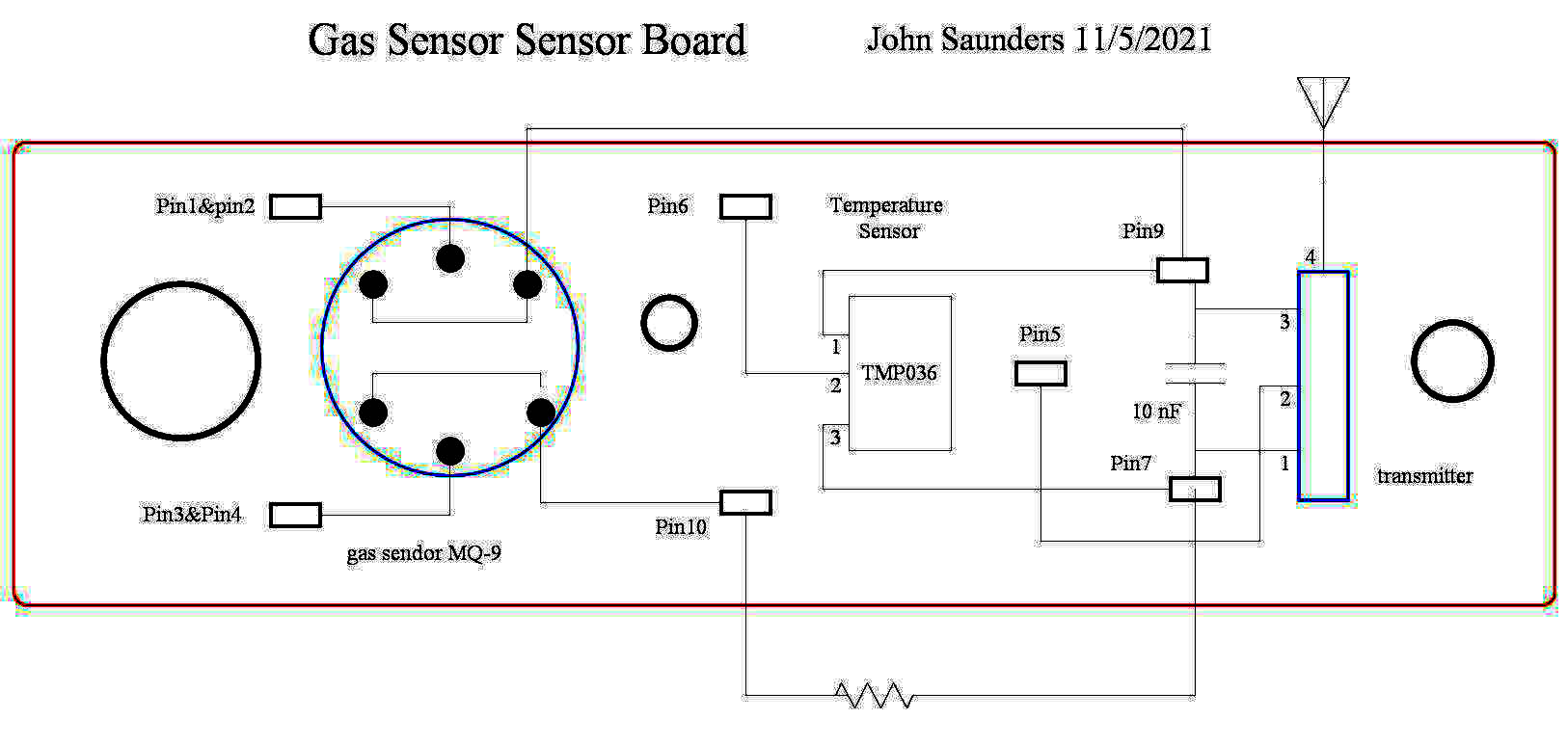
The rectangles are just hoops of stiff wire. The transmitter is a module with positive input for on-off modulation. The temperature sensor had to be moved way to the right bacause it could not be isolated from the sensor heat where it is shown.
|
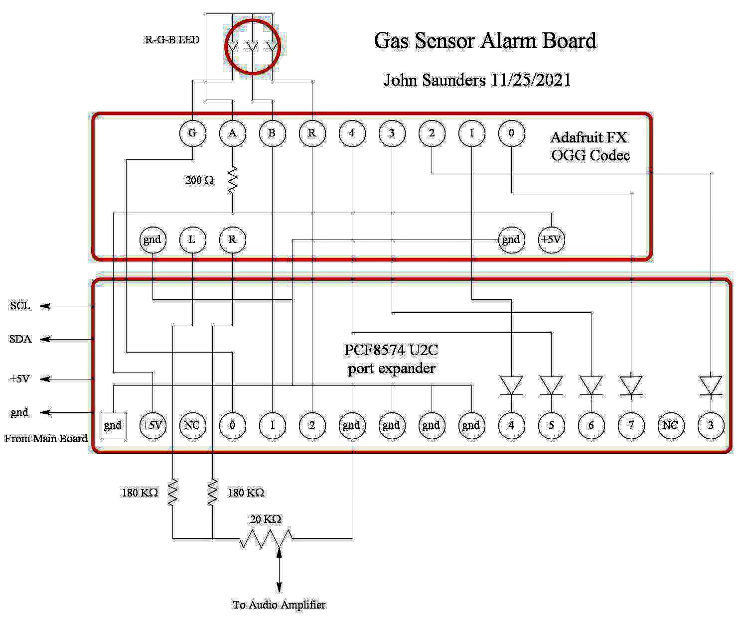
This comprises the ogg audio decoder and the 8-bit port expander. The diodes are there because the port expander is 5V and the audio board is 3.3V. It does have pull-up resistors since it is designed to be used with push-buttons. The potentiometer is a volume control.
|
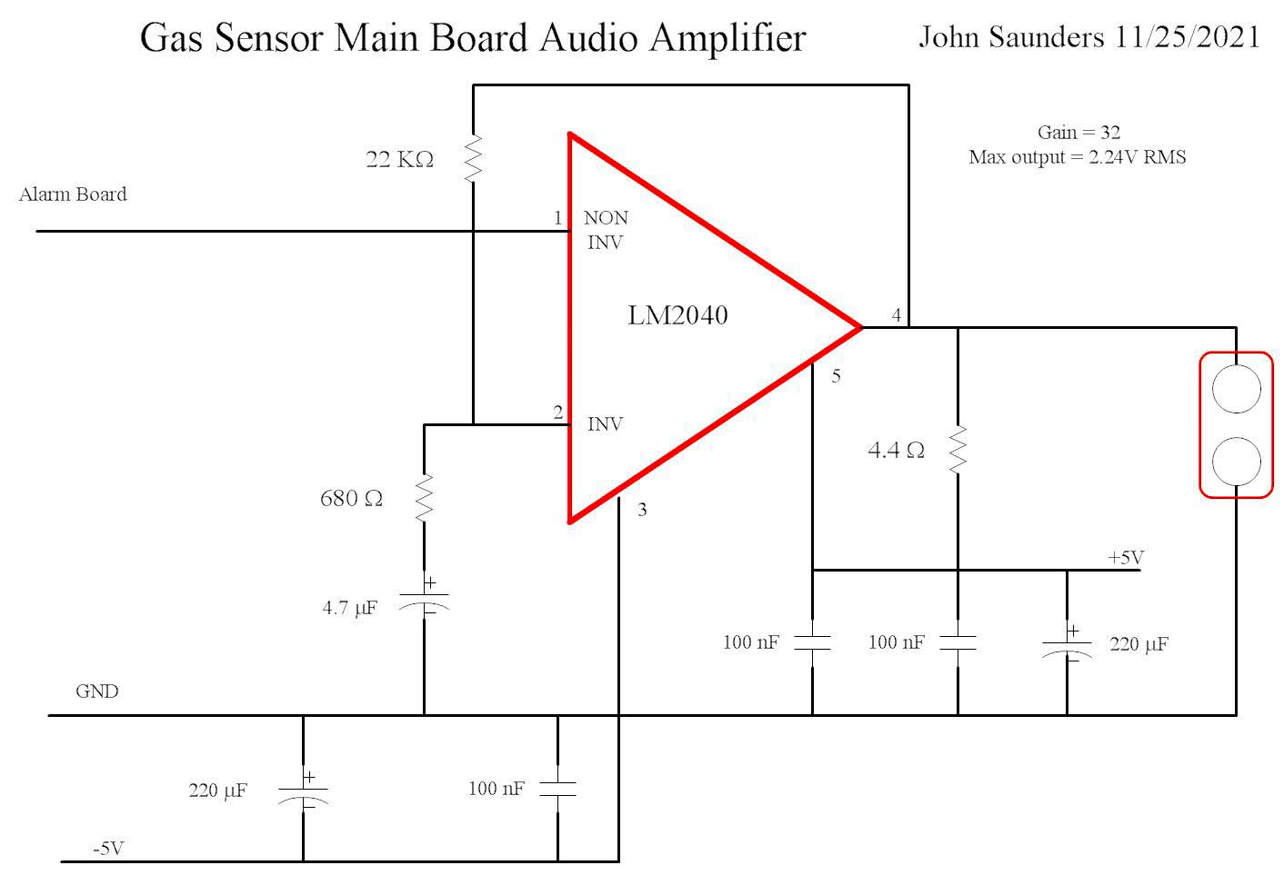
The gain is set to suit.
|