Removing three screws at the bottom allow the Display sub-assembly and attached Main Board to be removed.
This allows access to the Main Board with removal only of the three power, two speaker wires, and the ribbon plug.
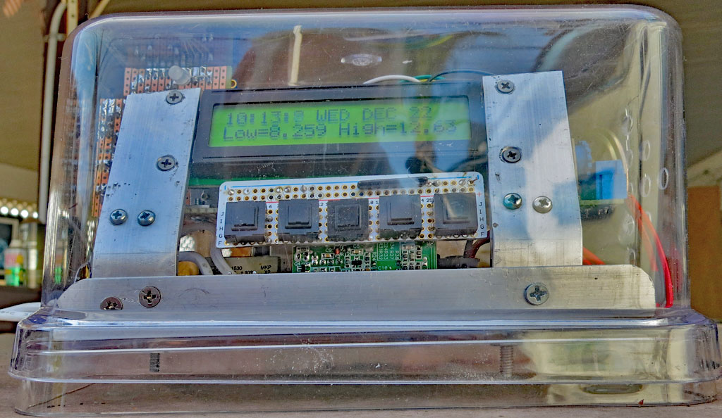
It shows the Sensor sub-assembly with its cover installed. The wire is the antenna.
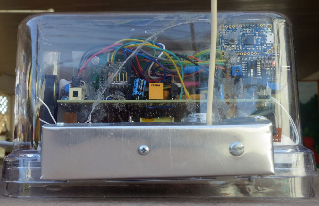
The assembly seen edge-on is the Alarm Board, which attaches to the Main Board with a single screw. It connects with five jumper wires.
Above the Alarm Board is the audio amplifier.
To the right of the Alarm Board is the plug-in RTC. which uses I2C. Hopefully its tiny, soldered-in, battery will last forever.
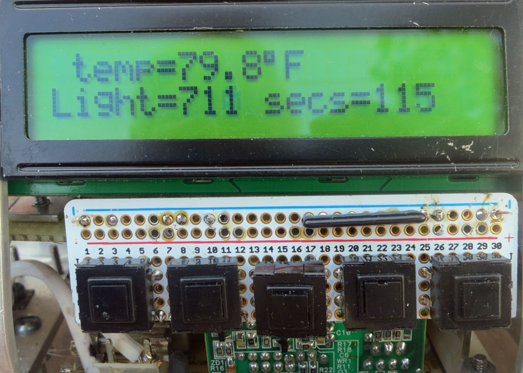
Next is the light sensor, its circuit, the 1.5V regulator I2C and the sensor heater relay.
Last is the plug-in Arduino processor and a whole mess of jumper wires.
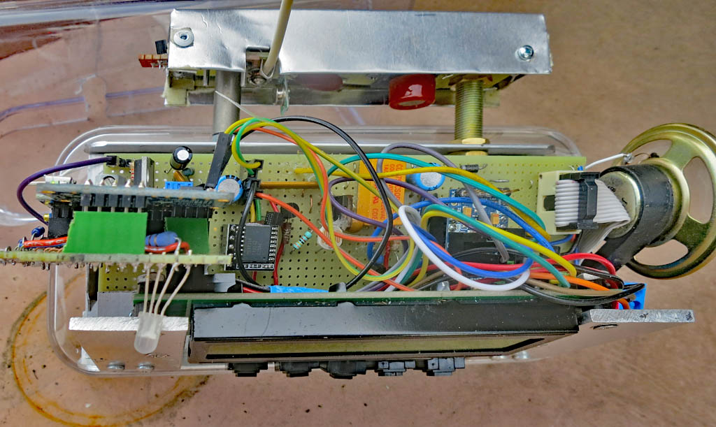
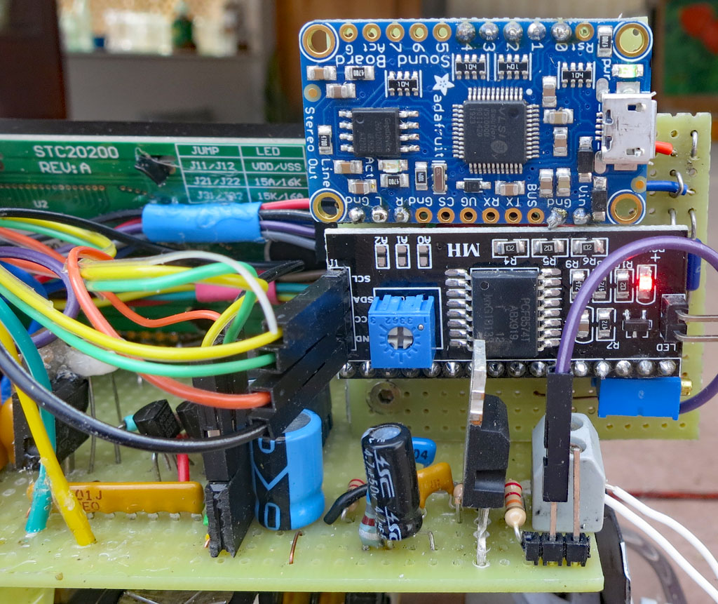
The top board is an audio decoder for files with the ogg extension, for which it has internal storage.
It selects a file with a name corresponding to the numbered pins on the top, and makes a sound signal for the audio amplifier when pulsed.
The lower board is an I2C 8-bit port expander wired to directly match the connector of many common LCD displays. In this application three outputs drive the LED and the other five go to the audio board.
The audio amplifier is in front of the Alarm Board
The RTC, the Light Sensor, its circuit, and the 1.5V regulator are in this photograph, but are difficult to make out.