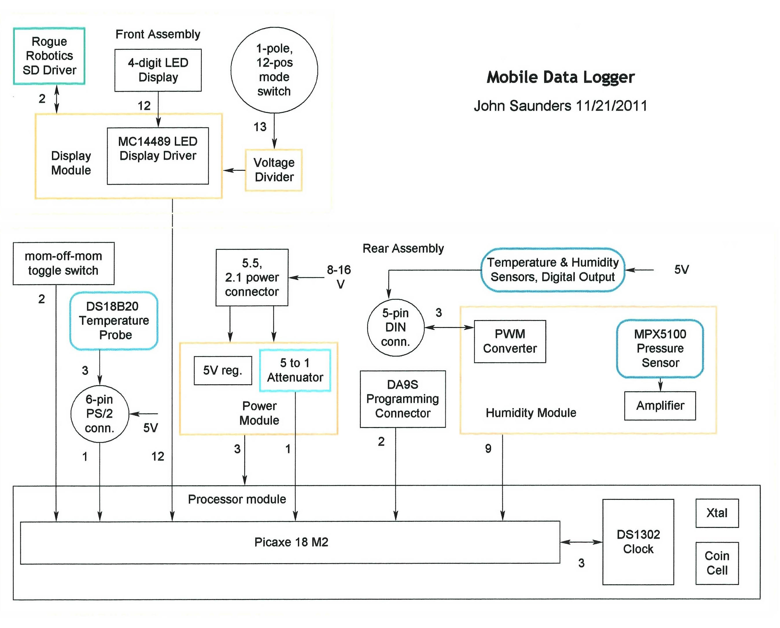
System Block Diagram |
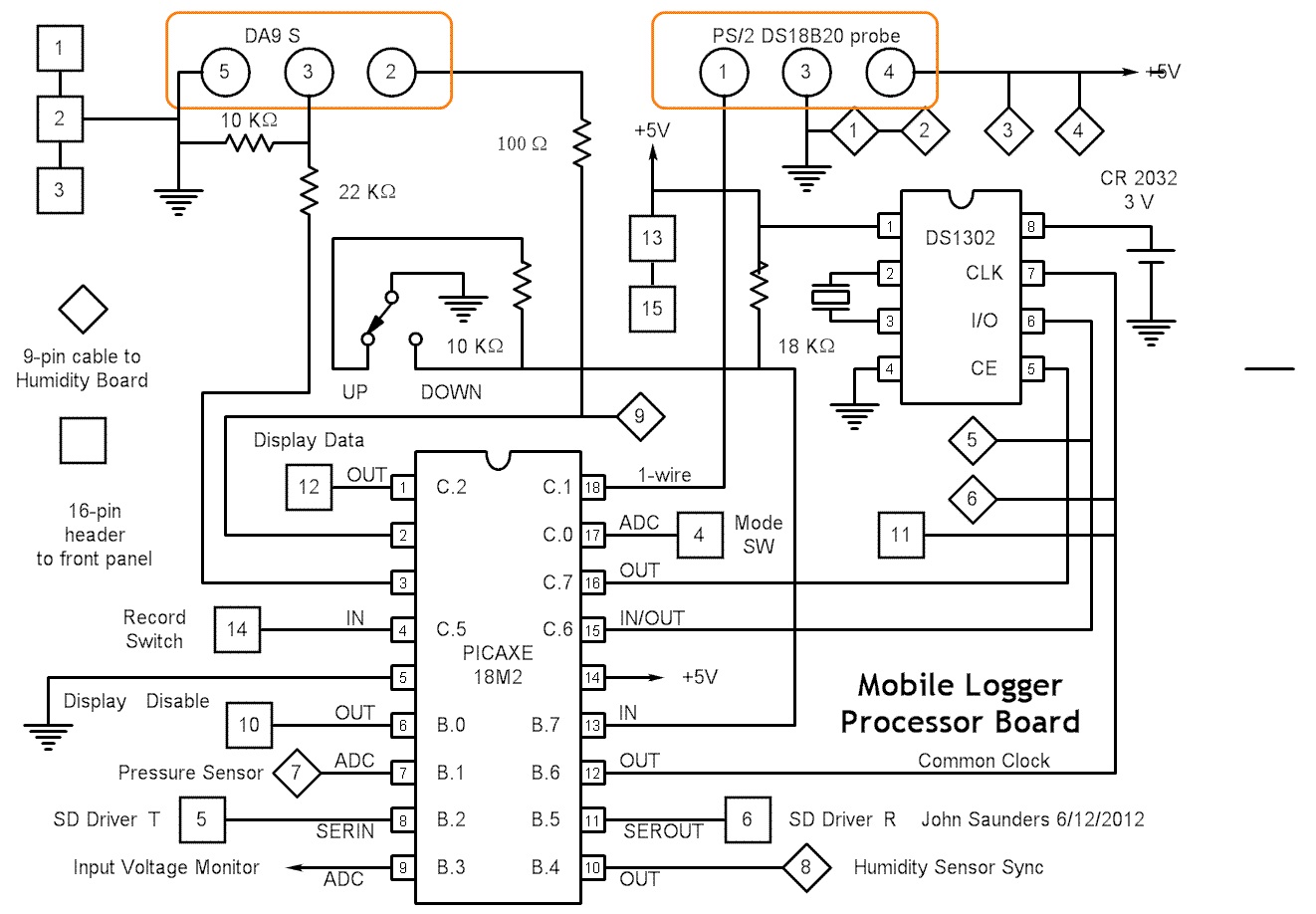
Processor Circuit Board |
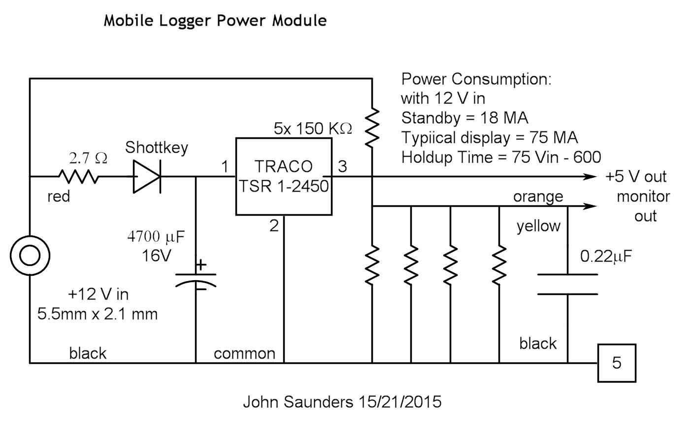
Power Module: the resistors are in a module |
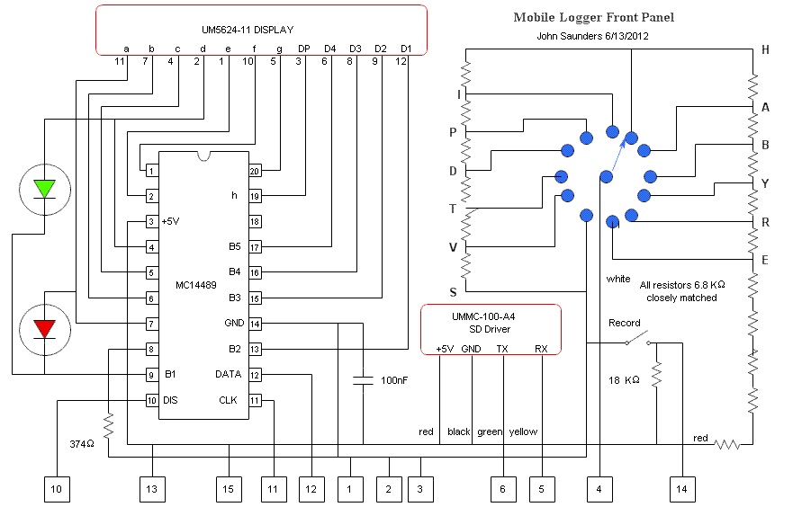
Front Panel:There are 2 small boards, plus the uMMC |
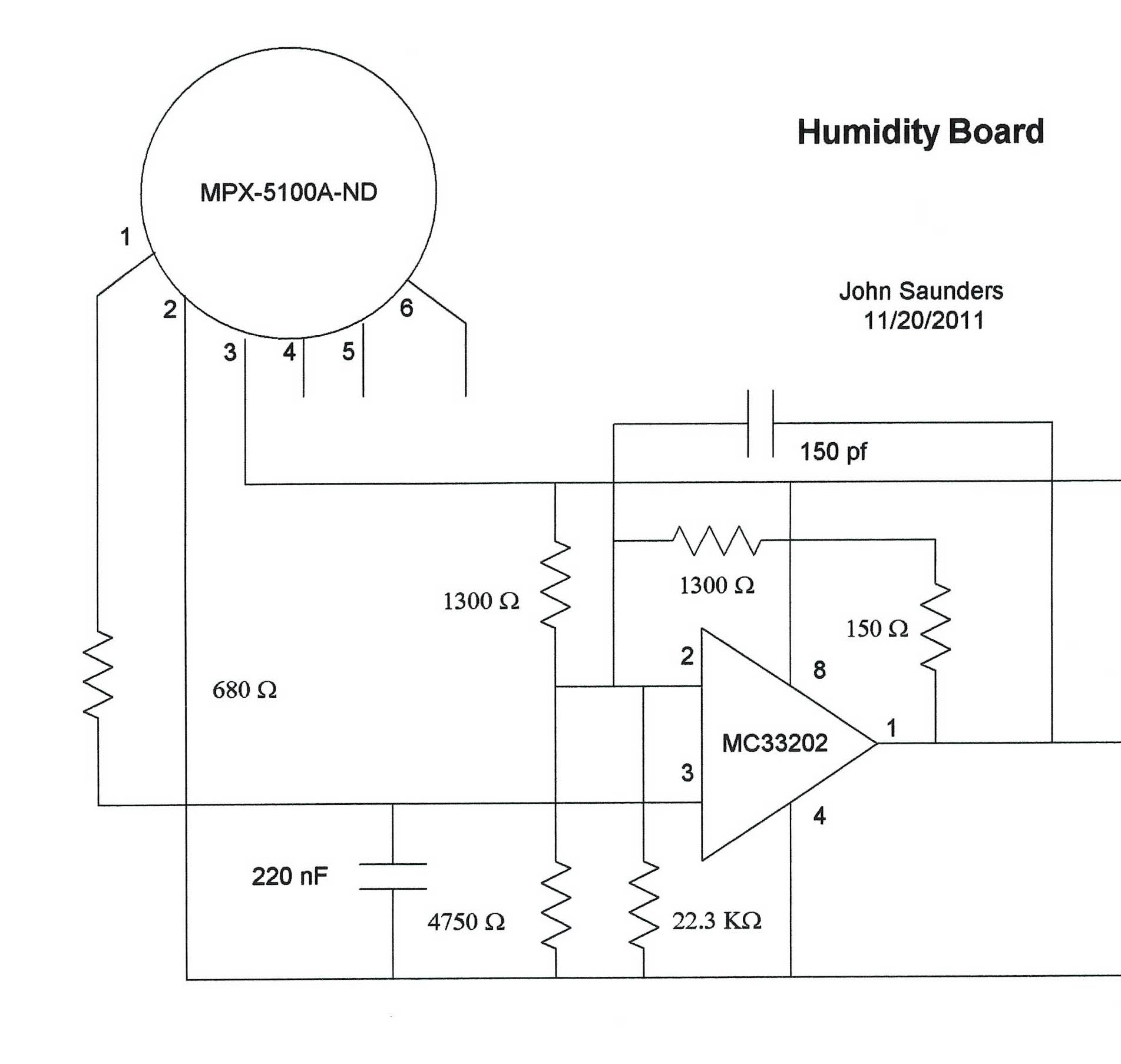
Pressure Sensor Circuit. The amplifier is used to improve the resolution, since not all the sensor's range is needed.There are better op-amps than the MC33202, but it is rail-to-rail. This is on the same board as the Humidity Interface. The resistors are all 1% |
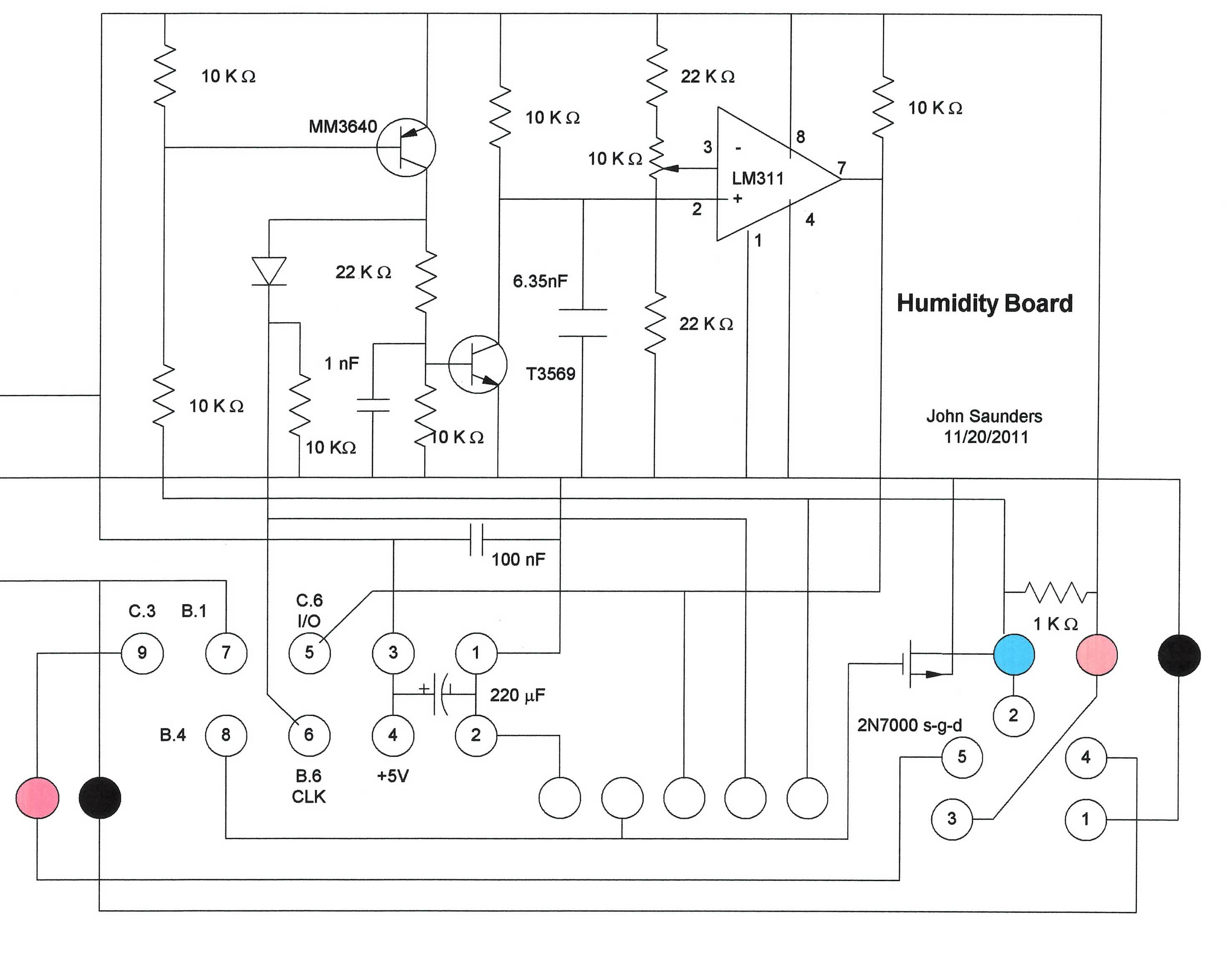
Humidity Sensor Interface CircuitThe pot is not needed - the PWM to NRZ conversion is not that critical. There are simpler circuits published, but this requires that the data and clock line be bussed with the Picaxe. Requires re-configurable Picaxe pins. There are capacitors to ensure adequate setup time for the DS1302.
The un-numbered pins are only for testing. The numbered pins go to the processor board. The colored pins go to a cable to an old-type DIN socket on the chassis for the AM2301. The resistors are accurate and are in modules. |