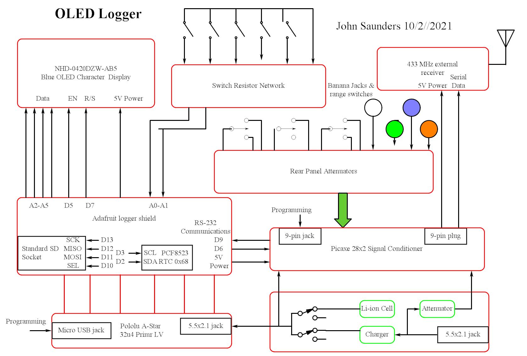
Block Diagram
These are the photos of the finished clock.
Here is the Picaxe program.
Here is the Arduino sketch.
Here are the circuit diagrams.
| This device is a substitute for the Weather Logger in that it receives all my messages in the 433 MHz band, displays them and logs them. It differs in that it is portable and therefore lacks the hard-wired inputs of the Weather Logger. |
|
It is battery-operated, self contained, and uses a 4 row by 20 column character OLED display. It consists of an external (to avoid interference) RF receiver with a wood base and three sub-assemblies which are housed in a metal clamshell case with a sloping cream-colored top. The top has a 20-column by 4 row blue OLED character display, and a 5-button rosette, which are connected via an interface board to the brown base by a ribbon cable. The base has three sub-assemblies: Power, Signal Conditioning, and Logging/Display.
A. The Power sub-assembly has a 3400 MAH Li-Ion cell which has a switch-mode charger.
The recommended charging power supply is the Challenger 12V, 3A with 2 pigtails.
When the battery is fully charged, the power consumption is 1.2W. It can run the Logger for about 19 hours on a charge.
B. The Signal Conditioner sub-assembly uses a Picaxe 28X2. It converts analog inputs to ASCII in volts with decimal point . 2. Rear panel: 3 jacks Green, Blue and Orange have 3 switched ranges: Up=28V, Center=52V, Down=12V. Scaling is automatically corrected in the conversion. A 4.096V reference is used. The White jack is direct 2V using a 2.048V reference. Analog inputs are digitized and transferred to the Logging/Display when it sends a command. 3. RF signals via 9-pin male jack. These are already digitized and verified messages are immediately transferred to the Logging/Display unmodified.
C: The Logging/Display uses an Pololu A-Star 32u4 Prime LV. which is compatible with the Arduino IDEl .
The 32u4 was selected over the Atmel328P-based UNO because its additional 512 bytes SRAM was needed.
The Pololu A-Star was selected over the Arduino Leonardo because it runs directly from the battery. |
| Front: |
|
These are the photos of the finished clock. |
|
Here is the Picaxe program. |
|
Here is the Arduino sketch. |
|
Here are the circuit diagrams. |