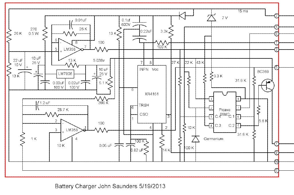
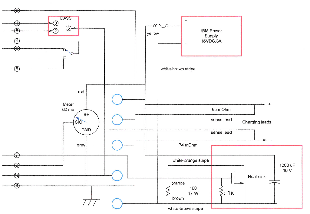
I am a little rusty about the XR-4152 circuit since I made it back in 2004, but I only had to change the current signal conditioner, which was previously used to measure temperature. It uses the negative battery lead as a shunt. Both leads have sense wires for accuracy. The meter sub-circuit is independent of the charging circuit, and will measure voltage without being plugged in.
The voltage circuit has an offset, giving a range of 10-16V.
The PICAXE 08M2 charging circuit digitizes the current and voltage signal conditioning outputs. It uses an algorithm based on battery voltage once a minute to establish a desired charging current. More frequently the measured current is compared to this set point to change the PWM duty-cycle to align them.