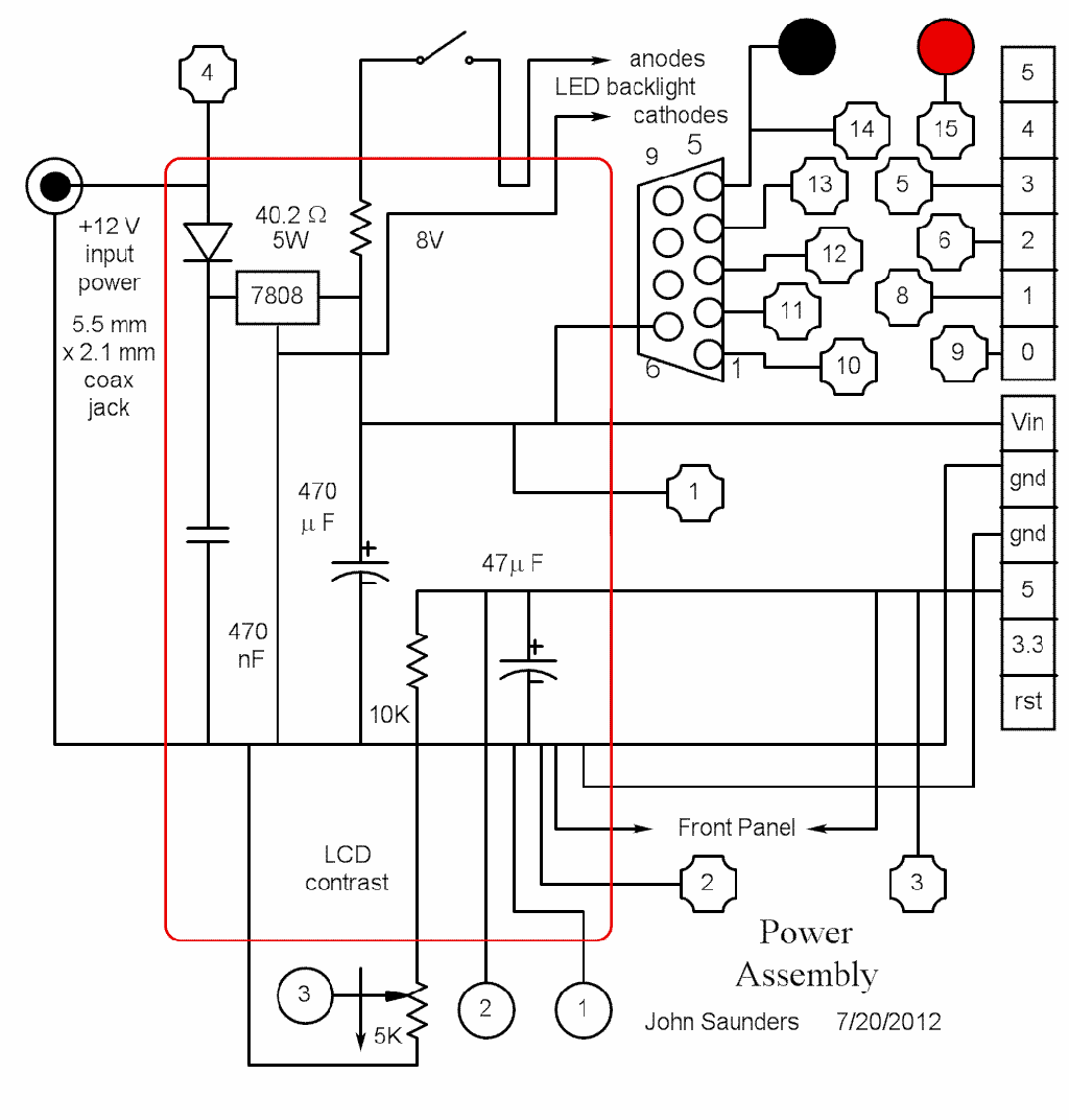
Apart from the regulator, this is just a place to center many of the interconnections..
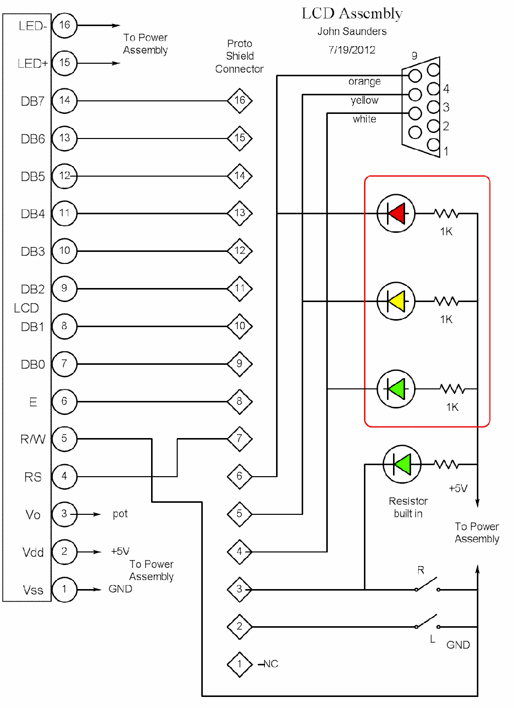
The switches and LEDs are here because they are mounted on the same front panel as the display. The "D" connetor, however, is at the rear. The two switches are momentary downwards, but latch upwards.
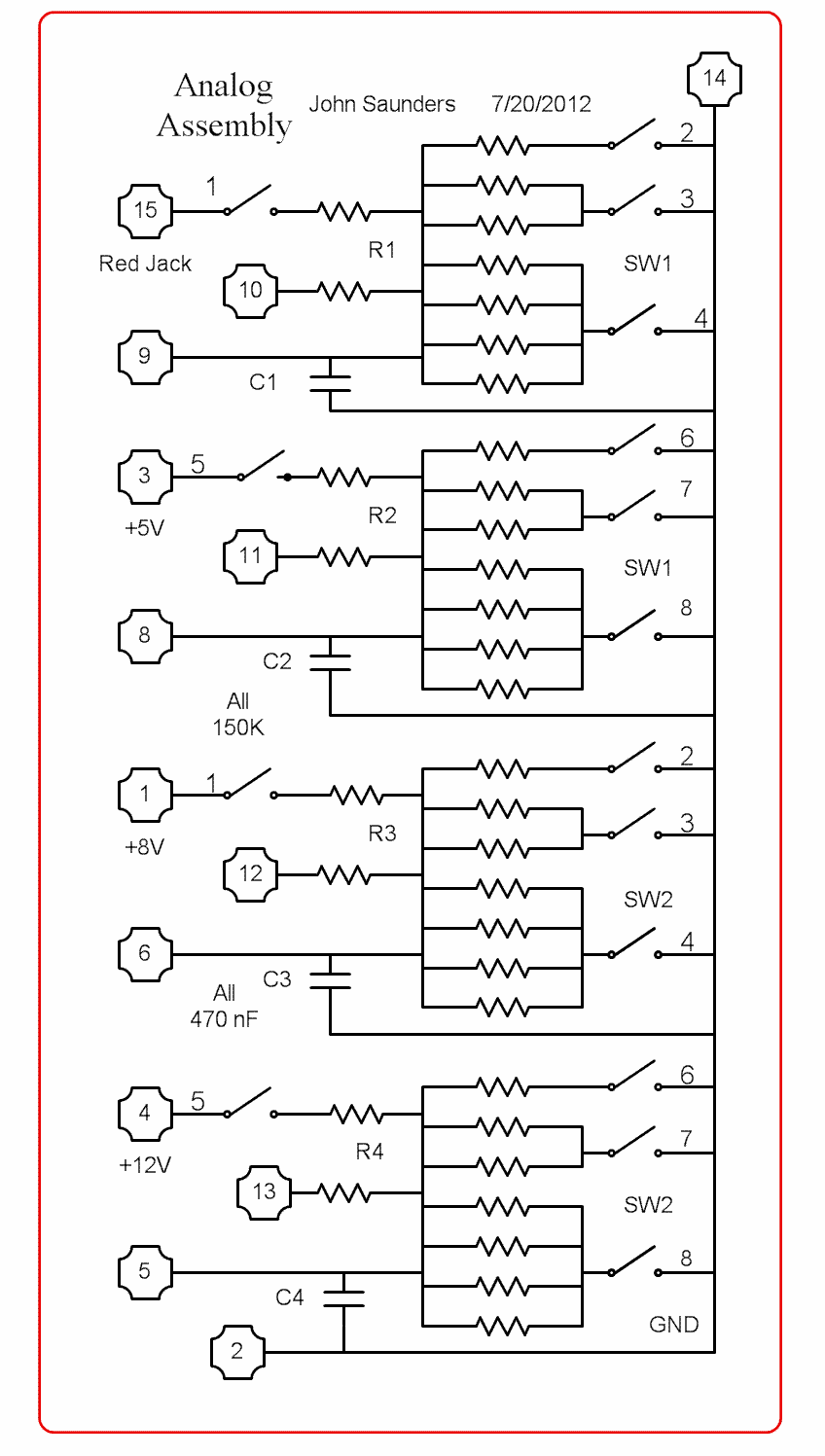
I like to buy assortments cheaply, in this case single in-line resistor packs and DIP switches. This design makes a virtue of the common connection and close matching of the resistor packs. It provides 8 ranges in 3V increments. Spare switch positions are used to optionally monitor the power supply voltages.
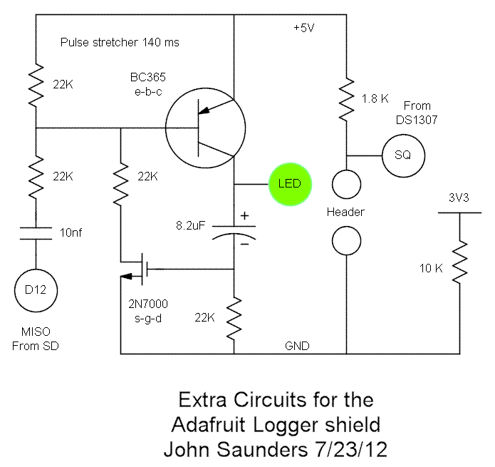
The Adafruit logger shield has spare pads for extras and two uncommited LEDs. I wired in a pulse stretch circuit to detect responses from the SD, which would otherwise be too short to see. I used discretes to save space. I included code to turn on the DS1307 square wave, but have not used it.
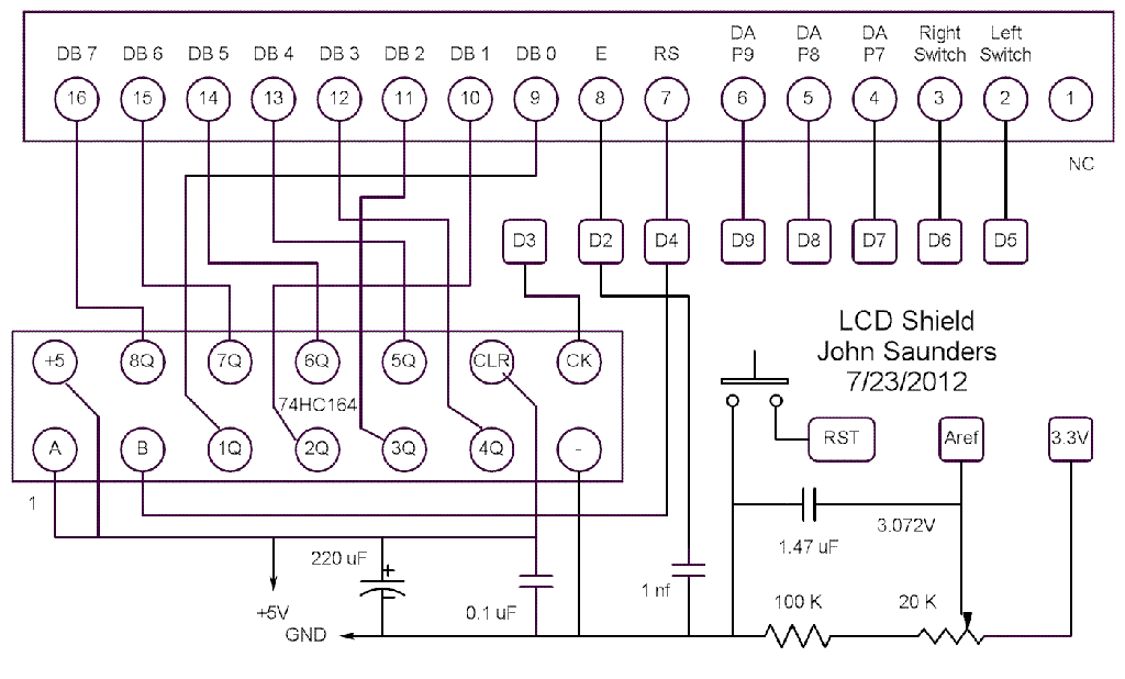
I have used this circuit before several times to save pins. Note the double use of D2. You don't have to use a '595, since the display itself latches.