In doing this I discovered the Adafruit website and bought their logger "shield", which was so much a better buy than the separate RTC and SD interface boards I had used in some of my Picaxe and Stamp projects. This was a more taxing experience, learning their libraries.
Wanting more digital inputs, I then bought a proto-shield and wired up a clone of a shift register circuit for the display from an earlier project. This had two learning curves. I could not then use the supplied "LiquidCrystal" library, and since its source code, and that of the underlying "print" class, were not available, I had to write the whole class from scratch. I should disclose I am a retired C++ (and Ada) Software Engineer, although rusty after 10 years. The second was that the SD SPI interface prevents using either the clock or MOSI lines for the shift register, and this took me some time to discover.
Eventually this grew from a learning setup into this real project. I appreciate the speed and capabilities of C++, but the SD and File libraries use up so much SRAM that I could not get all the capabilities I wanted in the same sketch.
Eventually I discovered a way to store constant data in the flash memory and keep it there. This was a hassle but enabled all of my desired features to be in the same program

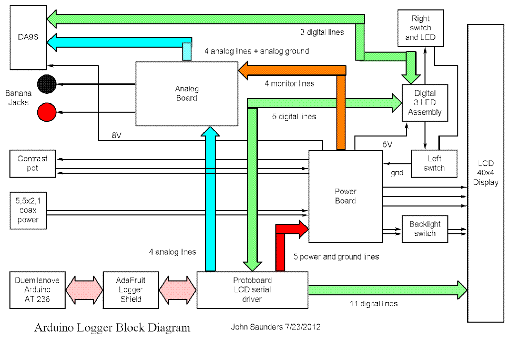
I elected to make it powered from 12 volts auto supply. I was forced to use another regulator because the one in the Arduino would overheat if driving the LED backlight. I used an intermediate 8V TO-220 regulator to avoid the wide swing of LED current if it was driven from the 12V supply.
The details are described in these links:
The remaining 4 analog and 3 digital I/O lines are brought out to a 9-pin "D" connector, plus a pair of banana jacks. I first tried out the C++ float capability, but decided to use the Arduino external analog-to-digital reference input at 3.072V from its 3.3 V regulator, so I could use integer arithmatic for conversion of the ADC readings to actual voltages.
There was space for 4 voltage dividers for the analog inputs, and I had the components, so I did this. Since I was not limited in code space, I added screens to set the analog ranges, the recording interval, and correcting the RTC. These settings are stored in the non-volatile RTC RAM.
Here are the circuit diagrams