A smaller board interfaces the display. A large board inputs the controls and interconnects everything.
No changes were necessary when substituting the Stamp II SX, as it has the same pinout.
|
|
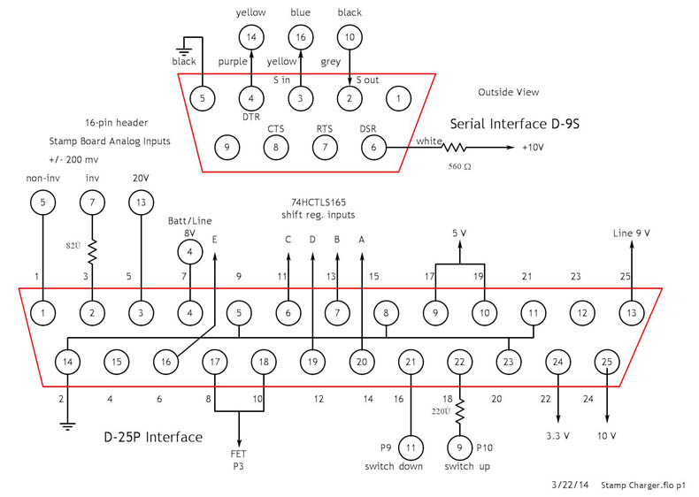
This device has three circuit boards. The processor board contains the Stamp II, a Real-Time Clock for real-time, a serial I/O interface and two 10-bit ADCs with signal conditioning for voltage and current. It has a sparate interface for programming A smaller board interfaces the display. A large board inputs the controls and interconnects everything. No changes were necessary when substituting the Stamp II SX, as it has the same pinout. |
|
|
|
|
|
|
|