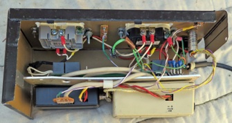
This is the chassis removed from its wooden case. It is open at the bottom and one side. This is a view from that side.
Down the center are the 4 relays, which use small quick-connect terminals.
The beige item is a 24V power supply. The receiver is in the blue container.
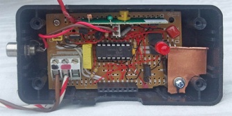
This is the inside view
This is the Receiver Board. The receiver module is at the top.
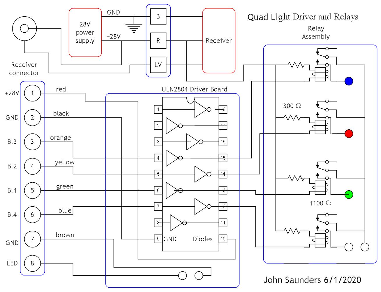
Here is the chassis circuit diagram. The mechanical relays shown have since been replaced by SSRs
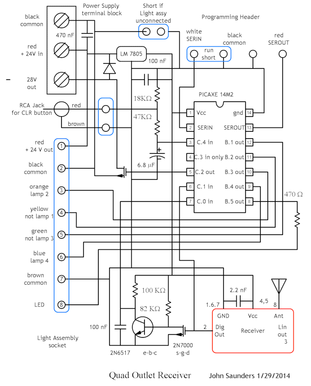
Here is the receiver circuit diagram:
Colors are for identification purposes only.
The "LV" codes control a 28V output socket for our "LAS Vegas" ornament, which replicates the fanous one on the "Strip".
Here is the program