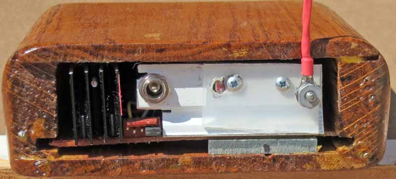
This is the in top view.The assembly slides out of the box.
This may be the last board I will solder from scratch since my glaucoma makes soldering tiring and the results are of poor quality. Notice I was forced to use thicker wire than the 30 awg wire-wrap wire of my previous projects.

This is the back view. Notice the programming header is exposed.
Here are the circuit diagrams. Yes, Victoria, I do know about multiplexing, see the Spa Display, one-chip solutions, see the Altimeter and the Mobile Logger, and PWM for dimming. However this static display is soothing and uses up old stock.
The 4 little triangulat LEDs are for the decimal points to track the segment brightness. These display modules have 2 LEDs in series per segment.
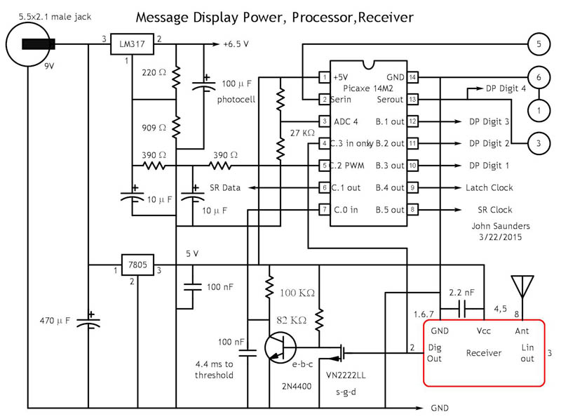

Control messages are also received. These determine what data to display by looking up an entry in EEPROM. If additional messages are added, this table would be extented. The new message length would be put into the LOOKUP comand in line 188.
Here is the program description: