Digital Ammeter Board Interconnections
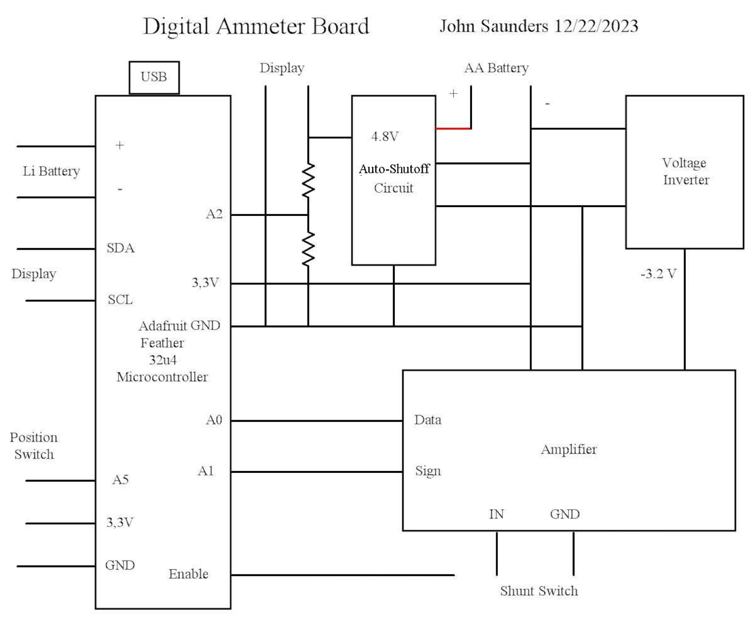
This diagram is of the board in the Digital Ammeter box.
This is bolted to 3 standoffs on the bottom of the box.
The following circuits are described elsewhere:
- Auto-Shutoff circuit.
- Voltage Inverter.
- Amplifier.
The micro-controller plugs into sockets soldered into the board. It is held down by a screw.
Its pins are mostly extended with receptacles on top, five of which connect elsewhere on the board by a “paddle”, and two to the front panel.
The 2 resistors to measure the AA battery voltage are soldered to the board under the micro-controller. They are matched, as are two internal to the micro-processor to measure the lithium battery voltage on pin D9 AKA A9.
The AA battery is in series within the Keep-Alive circuit which permits this 4.8V connection to be connected to the display only if 3.3V is present. This prevents AA battery drain when the ammeter is off.
The Voltage Inverter is a switched-capacitor circuit which mirrors its positive input to almost the same voltage, but negative. This is needed by the amplifier for negative and AC inputs.
The amplifier consists of a precision low-offset preamplifier driving a “Perfect Rectifier” circuit. This results in a positive output with a peak value near to the 3.3V A-TO-D reference voltage for every range.