Digital Ammeter System
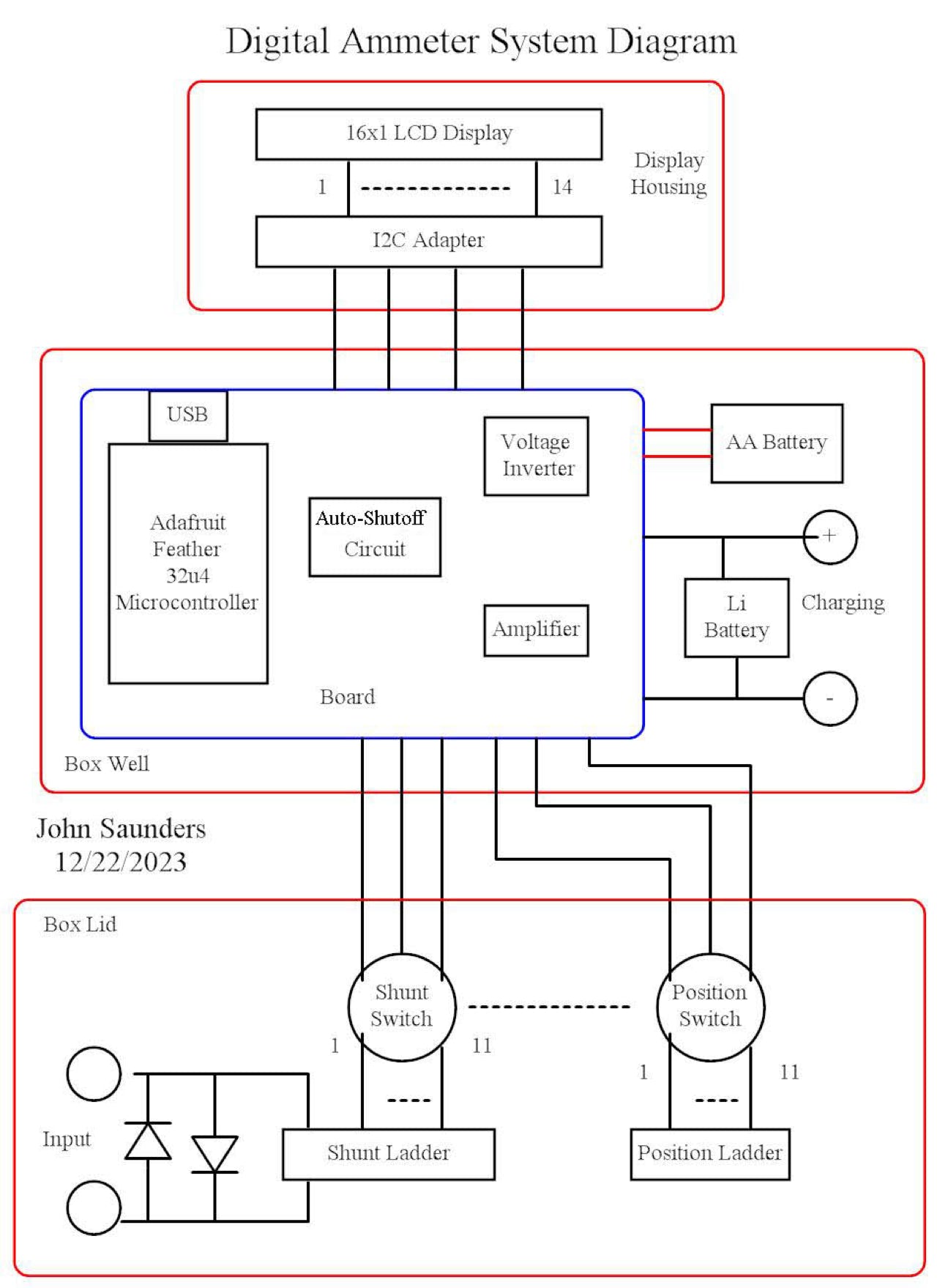
The Ammeter consists of a box, its top panel and a display assembly.
The box contains the two batteries, and a board containing all of the active circuitry.
The batteries are housed in holders.
The top panel contains the range switch which has two identical wafers and the input sockets.
One selects taps on the shunt resistor assembly for 10 positions, and one is ground.
This latter shuts down the device.
The other switch connects to a ladder of 11 equal resistors to enable display of the range units. This also allows the micro-controller to compensate for errors in the value of the shunt resistors on a per-range basis.
The input is by-passed by power diodes to avoid overheating of the shunt resistors if a high current is applied at a more sensitive setting. These do not conduct at 50 mv.
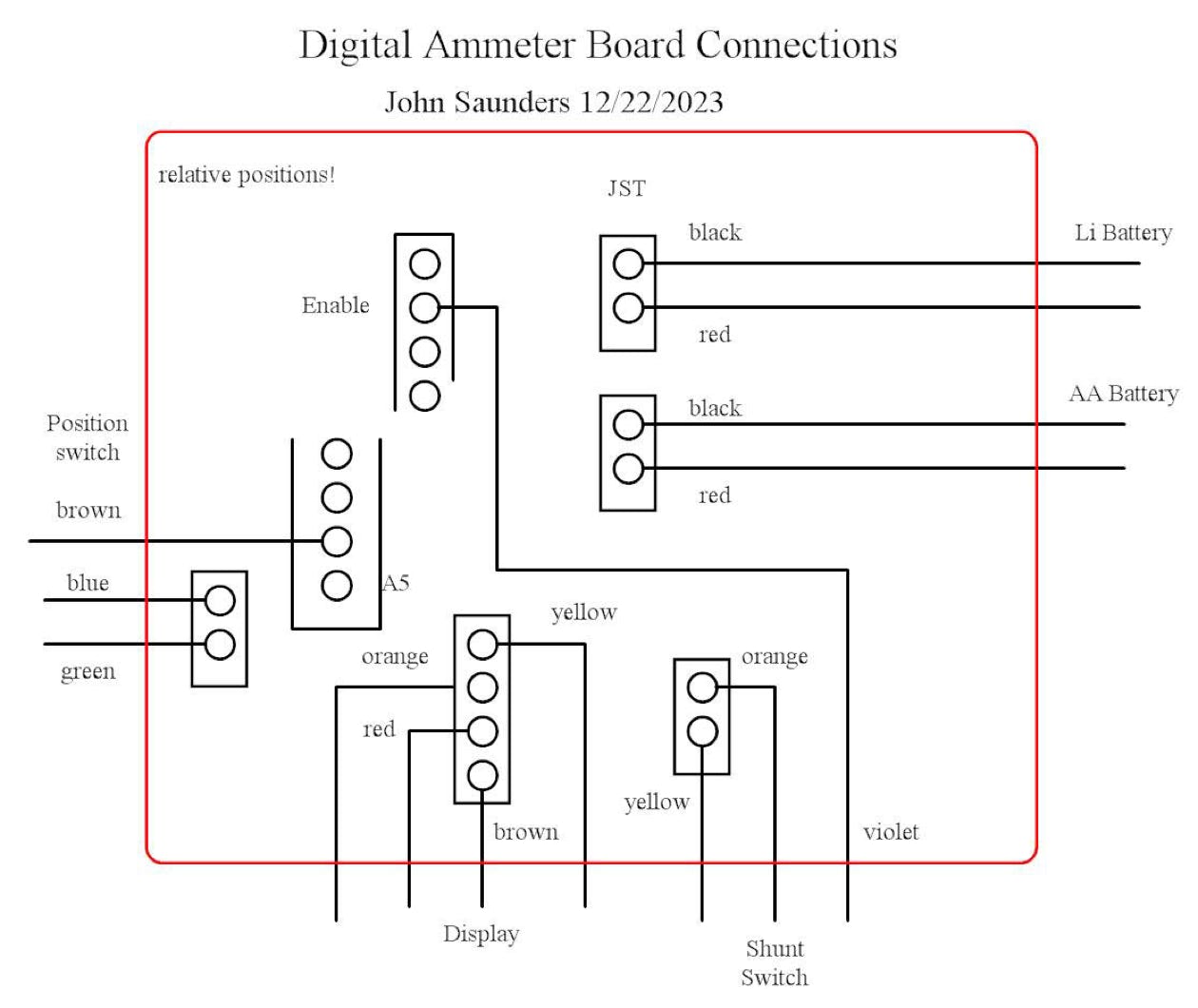
The Switch, the Display and the two batteries are connected to the board containing the Micro-controller, the Power Circuits and the Amplifier by cables with connectors.
The Display Housing is fastened to the back of the Box and can be rotated for best contrast.